Oak Ridge National Laboratory Phase 2a Thermal Testing: Impact of Mass Wood Walls on Building Energy Use, Peak Demand, and Thermal Comfort
The Background Information
Measurement of the thermal performance of mass timber is undergoing significant change and improvement. Using the results of decades of studies and experience in practice, crucial factors are being integrated into modern methods of determining the heating and cooling demands in mass timber buildings.
The International Mass Timber Alliance (IMTA) has partnered with Oak Ridge National Laboratory (ORNL) to assess the thermal performance of mass timber CLT (cross-laminated timber) wall components. The first phase of the study investigated the heat flux through individual panels of mass timber CLT under a range of exterior climatic conditions. The results were compared to those for standard-frame wall materials under the same test conditions. Our Phase 1 article presents the findings of Phase 1.
Phase 2 of the study investigated the thermal performance of mass timber CLT wall components in enclosed space models. The focus was on the amount of energy used to maintain interior thermal comfort levels in spaces of different sizes. The results were compared to those for standard-frame wall components under the same test conditions.
This article presents the methods and results of Phase 2a of the study, which used a 1.00 cubic meter enclosed space model to evaluate how thermal comfort can contribute to new findings associated with energy savings in mass timber. This novel thermodynamic approach brings the assessment methodology of convectional two-dimensional static assessments to inner and outer dynamic, thermodynamically holistic, and three-dimensional multi-heating systems.
Materials & Methods
The test chamber used in the study was the Large-Scale Climate Simulator (LSCS) at ORNL (Figure 1). ORNL staff conducted simulations to design appropriate climate chamber test parameters for convective and radiative heating systems.
IMTA provided the test cubes, heating elements, and sensors for the study.
Cube Specifications
Four 1.00 cubic meter test cubes were constructed – two with mass timber CLT envelopes and two with standard-frame material envelopes to match the methodology of Phase 1.
The CLT panels were pre-cut and assembled by Eagle CDI (Seymour, Tennessee). The design specifications called for standard-frame and 4″ and 6″ CLT to match the Phase 1 design. CLT cubes were each 6-⅞” inches thick.
Oversized side panels were similarly installed. Following installation of study instruments within the cubes, the original top panel was placed on the gasketed inner cube. A second, oversized top panel was then installed and screwed down at the edges to fully compress the tops on the gaskets.

Figure 1: Layout of ORNL of the Large-Scale Climate Simulator
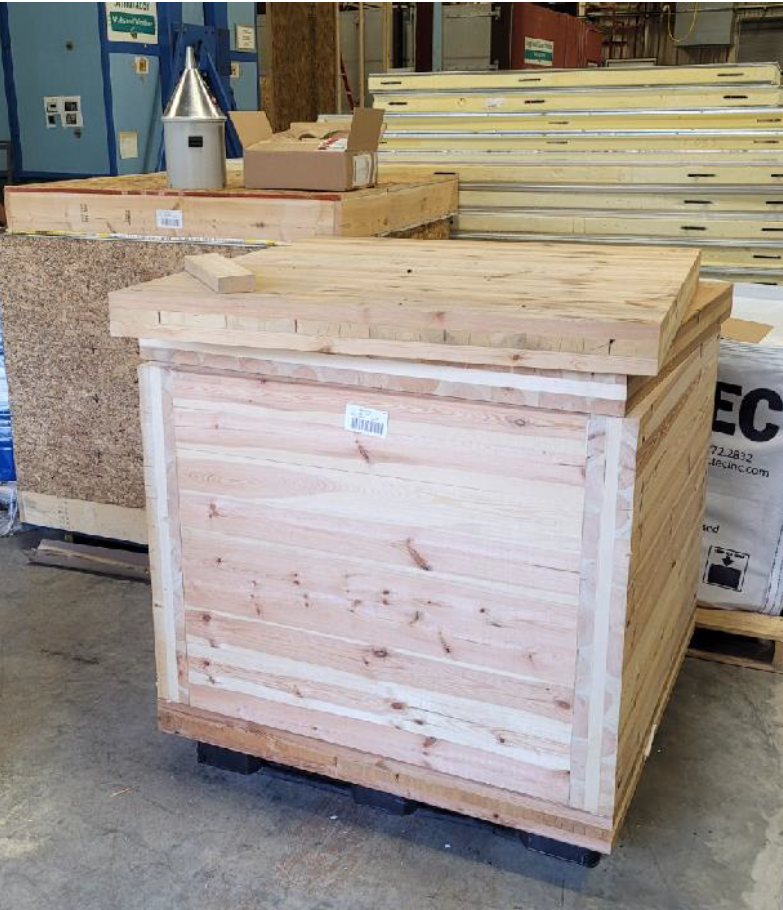
Figure 2. One of the CLT cubes has the tops for both. Ready for the testing equipment to be installed.
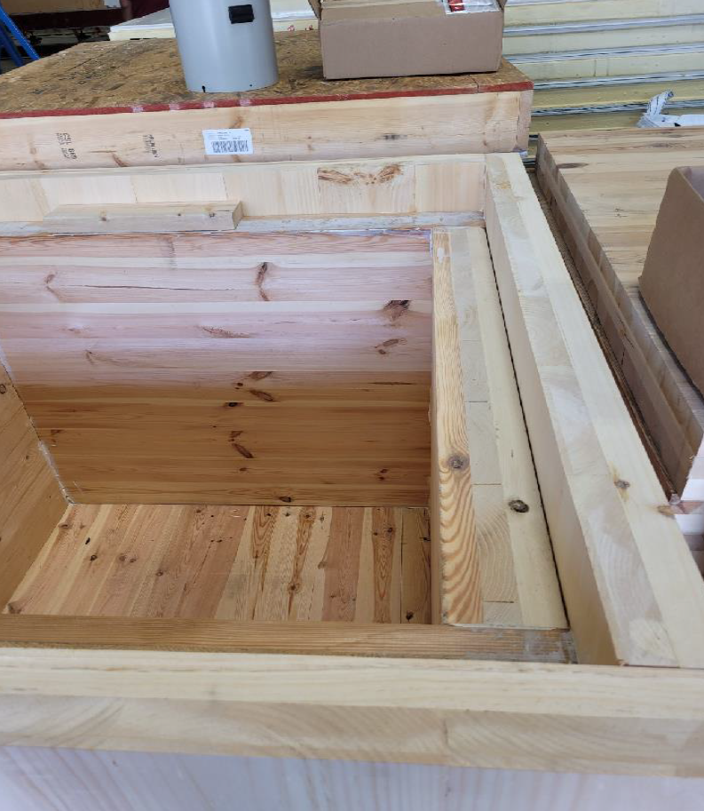
Figure 3. The tops of all four cubes were not fastened in place to allow ORNL staff to install the technology needed for the tests. The additional panels for the 6-⅞” cube provided a different challenge. The existing cube top would be set down into and on top of the existing cube on gaskets, and the new top would be installed, covering all and gasket and screwed down at the edges to fully compress the tops on the gasket.
Cube Instrumentation
Cube instrumentation was developed and provided by IMTA Principal Investigator Carl Timo Manz (CT Manz Consulting Inc., Frankfort, Germany). The instruments used were heating units, sensors, and control units.
Infrared heating panels from the Cambridge Graphene Centre were used to build radiative and convective heating systems. For the convective systems, an aluminum heater casing with fan-driven air outlets was used to shield the infrared heating panels and provide convective heating. For the radiative systems, the infrared panels were not shielded in order to provide radiative heating.
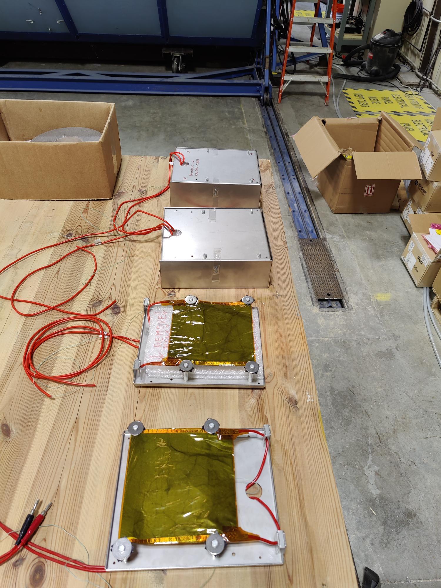
Figure 4. The instrumentation was designed for the 1m cubes based on the science used by Dr. Timo Manz in his studies on thermal mass wood in Frankfurt, Germany. His team packaged the components and shipped them to ORNL.
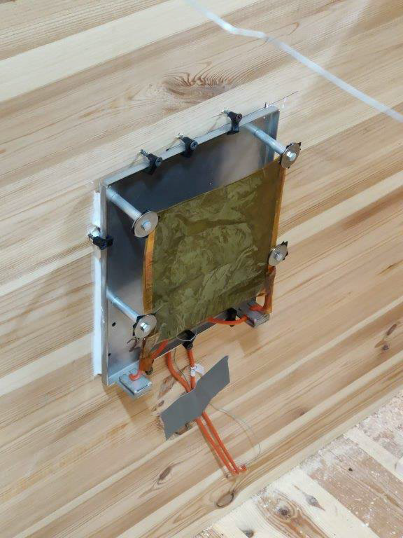
Figure 5. Unshielded graphene units for radiative heating.

Figure 6. Shielded graphene units for convective heating
The sensors recorded wall surface temperatures and interior air temperature so that the model operative temperature could be determined (all wall surface temperatures plus the interior air temperature). The sensors continuously transmitted data to the control unit.
The control units monitored and adjusted the heating units according to the settings of the different heating methods, e.g., fixed inner air temperature and/ or operative temperature.

Figure 7. The sensors (left) “pointing” to each wall, held by an aluminum rod. This unit measures the wall surface temperatures and the air temperature; thus, it is capable of sensing room temperature as well as operative temperature (operative temperature = all wall surface temperatures and the air temperature) and passing the data to the Controls unit, which is capable of controlling the differentiated heating methods (fixed inner air temp. and/ or operative temp.).

Figure 8. Control unit.
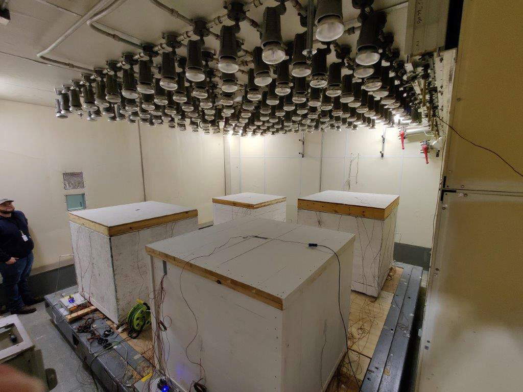
Figure 9. The completed cubes in the climate chamber.
Test Conditions
The completed cubes were placed into the LSCS climate chamber where tests were conducted under summer and winter climate conditions. Dynamic outer conditions such as weather, day-night changes, seasonal differences, and solar radiation were introduced to the climate chamber.
The summer test conditions are listed in Graph 1 below. Both the 4″ and 6″ wall thickness cubes were used in the summer tests.
The winter test conditions are listed in Graph 2 below. The tests were performed using the 6" wall thickness cubes.
In both the summer and winter tests, two types of temperature controls were evaluated:
- Operative temperature control in which the heater maintains an operative temperature of 19°C inside the cube
- Air temperature control in which the heater maintains an air temperature of 19°C inside the cube
The Results
Laminated Timber vs. laminated wood), the heating setting (convective vs radiative), and control (air temperature vs. operative temperature) were analyzed for cubes with wall thicknesses
Summer Test Results
The impact of the cube wall type (cross-laminated timber vs. laminated wood), the heating setting (convective vs. radiative), and control (air temperature vs. operative temperature) were analyzed for cubes with wall thicknesses of 4″ and 6″ .
Summer Test Graph 1 depicts the climate chamber air temperature throughout each of the four summer test runs.
Highlights of the findings include the following:
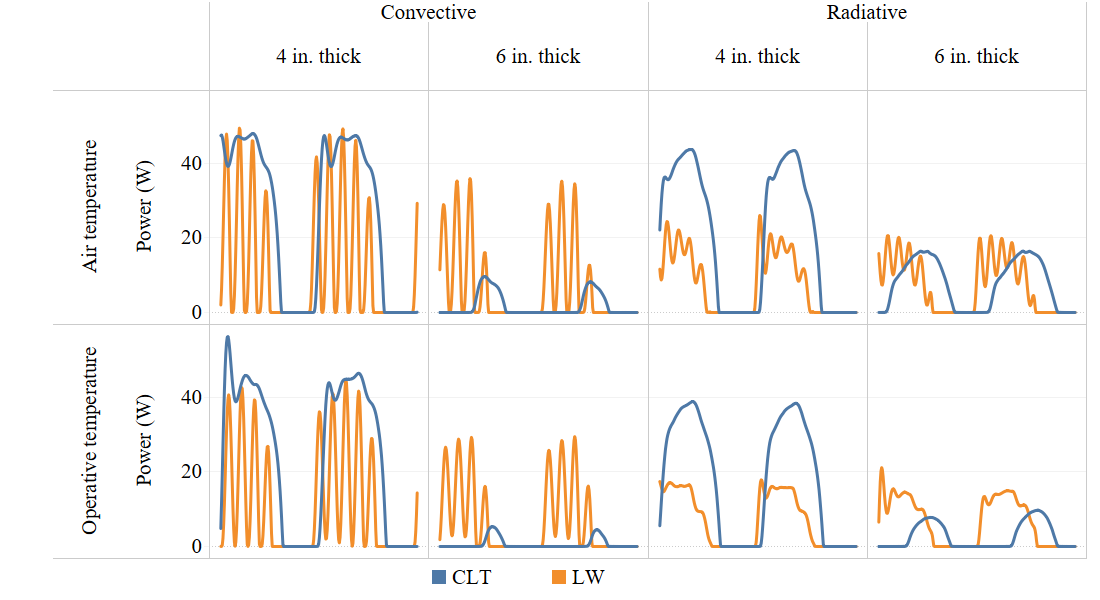
- Heater energy use for 4″ wall CLT and LW cubes was comparable under convective heating, while 4″ LW wall cubes had less energy use than CLT walls under radiative heating conditions.
- In the 6″ wall cubes, heater power use for CLT walls was lower than for LW walls with radiative heating, and much lower with convective heating.
- The lowest heater power use was noted for 6″ CLT walls with convective heating, followed closely by 6″ CLT walls with radiative heating. A time lag was also noted in heater energy use for the CLT cubes.
- The difference in heater power use for control of air temperature versus operative temperature was negligible.
Summer Test: Graph 1
Summer Test: Graph 2
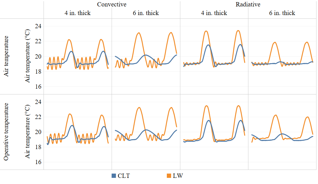
Overall there was greater fluctuation of air temperature in the LW wall cubes compared to the CLT wall cubes. Additionally, the 6″ CLT wall cube had less fluctuation in air temperature compared to the 4″ CLT wall cube. This is due to the thermal mass of the CLT stabilizing the temperature inside the cube.
The data also showed a significant benefit for 6″ thick CLT walls for maintaining occupant comfort.
Winter Test Results
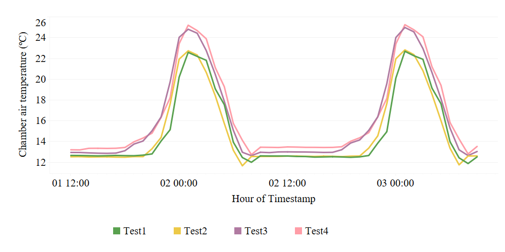
The winter test data selected for analysis was for a period of 24 hours such that the climate chamber air temperature diurnal cycle is similar to what was done for the summer conditions tests.
The chamber air temperature during the tests for the selected data is shown below.
Conclusions
Mass timber wall assemblies showed a significant impact of thermal inertia compared to lightweight walls. The results demonstrate that the conventions for rating insulation products do not apply to mass timber walls and that there is no linear relationship between the thickness of the mass wall and its thermal performance.
The 1.00 cubic meter cubes tested in the LSCS furthered the findings of the Phase 1 flat wall panel tests. It is anticipated that the next phase of enclosed cube studies will support savings in total annual energy use with improved thermal comfort and substantially fewer uncomfortable hours. As a significant element of this study, mass timber walls may reduce peak demand by up to 50%.
This could reduce the required wall thicknesses of mass timber buildings, potentially lowering the overall embodied carbon of the building. Ultimately, this research will support the decarbonization of buildings by supporting the use of mass timber in buildings.
ACKNOWLEDGMENTS
The information presented here was originally published in April 2022 by ORNL Staff of Mikael Salonvaara, Emishaw Iffa, Andrè Desjarlais and Jerry Atchley under CRADA NFE-20-08326.
This project was carried out in partnership with the International Mass Timber Alliance (IMTA) who provided the test panel assemblies. Mr. Robert Pickett, IMTA secretary, and Dr. Carl Manz, CT Manz Consulting, Inc. provided technical support to the project.
